- Joined
- Apr 26, 2018
- Messages
- 714
What works best ?
Getting ready to purchase and install a Powerlogger & 3 Bar MAP sensor on my 85 Hot Air with a digital dash. I understand that I need a 5 vdc source for the MAP since the digital dash cars don’t have the adequate wiring. I do not want to cut into the existing wire harness. As I see it, the two best options would be the Caspers - Sealed 12v to 5v Converter Module & MAP Sensor Splice or the Alkycontrol - TPS Harness.
Option 1.
Caspers Converter Module Sealed 12v to 5v Converter Module
Caspers MAP Sensor Splice – 84/89
MAP Sensor Splice - 84/89
Seems I would need the Caspers MAP Sensor Splice to complete the install. The question is just how long the pigtails are on the Sensor Splice and would the wires reach the analog input block of the PL (behind the glove compartment) assuming the MAP Sensor will install on the PS Fender where the existing Hobbs Switch lives ???
Option 2
Alkycontrol – TPS Harness
TPS Harness — ALKYCONTROL
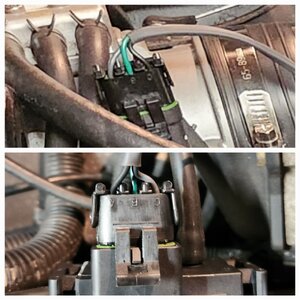
I like this option, but the question I have is the setup is for an 86/87 TPS. The TPS lever is reversed on the 86/87 compared to the 84/85. Not having the 86/87 wiring diagram, will the male Plug in & wires on this harness matchup with the 84/85 TPS for the 5v supply or are the terminals reversed too (wires in reversed slots) ???
84/85 TPS
A – BLK [return]
B – DK BLU [throttle position input]
C – GRY [5v supply]
Getting ready to purchase and install a Powerlogger & 3 Bar MAP sensor on my 85 Hot Air with a digital dash. I understand that I need a 5 vdc source for the MAP since the digital dash cars don’t have the adequate wiring. I do not want to cut into the existing wire harness. As I see it, the two best options would be the Caspers - Sealed 12v to 5v Converter Module & MAP Sensor Splice or the Alkycontrol - TPS Harness.
Option 1.
Caspers Converter Module Sealed 12v to 5v Converter Module
Caspers MAP Sensor Splice – 84/89
MAP Sensor Splice - 84/89
Seems I would need the Caspers MAP Sensor Splice to complete the install. The question is just how long the pigtails are on the Sensor Splice and would the wires reach the analog input block of the PL (behind the glove compartment) assuming the MAP Sensor will install on the PS Fender where the existing Hobbs Switch lives ???
Option 2
Alkycontrol – TPS Harness
TPS Harness — ALKYCONTROL
I like this option, but the question I have is the setup is for an 86/87 TPS. The TPS lever is reversed on the 86/87 compared to the 84/85. Not having the 86/87 wiring diagram, will the male Plug in & wires on this harness matchup with the 84/85 TPS for the 5v supply or are the terminals reversed too (wires in reversed slots) ???
84/85 TPS
A – BLK [return]
B – DK BLU [throttle position input]
C – GRY [5v supply]
Last edited:

 I bought both TPS Harness and Caspers - Sealed 12v to 5v Converter Module not really knowing what I would be getting into and just wanted to cover the bases. Thanks for the heads up on the length of the TPS harness. My thought was exactly as you described and intended to install the 3-Bar MAP by the Hobbs Switch. I was just going to use the vacuum from the Hobbs switch and not have the boost lights on the dash since I have an AEM boost gauge which uses the port at the front of the intake manifold. I am now thinking going your route with the MAP on the DS fender and teeing into the port on the manifold for the vacuum source. Since the Alky Control TPS Harness is for the 86/87 my one concern was the wiring compatibility not knowing the configuration (Blk, Blu, Gry) on an 86/87 TPS. Since you are one step ahead of me, I'll wait until you get your MAP hooked up and see what you report back. By not having my car in front of me, I'm just guessing at this point.