I have not checked the fuseable links, Good diagram i have multiple Service/shop Manuals for our cars, what im interested in is if anyone might know the schematic to the Ignition switch*
Rick, move the cam sensor like if it might possibly be 180* out? Wouldnt it still turn on just run rough?
I set the cam sensor as usual 25* atdc, #1 piston on top. Set cam sensor window facing driver side headlight dot on the gear facing passenger side, turn clockwise 1/2 a turn the turned counter clockwise till light on the cam sensor tool turns on lock it down.
Checked reluctor ring even changed the cam sensor to a new one i had with no play at all. Cap is new as well.
I did not manually check the cap with a screwdriver trick but if its reading thru the cam sensor tool should be fine?
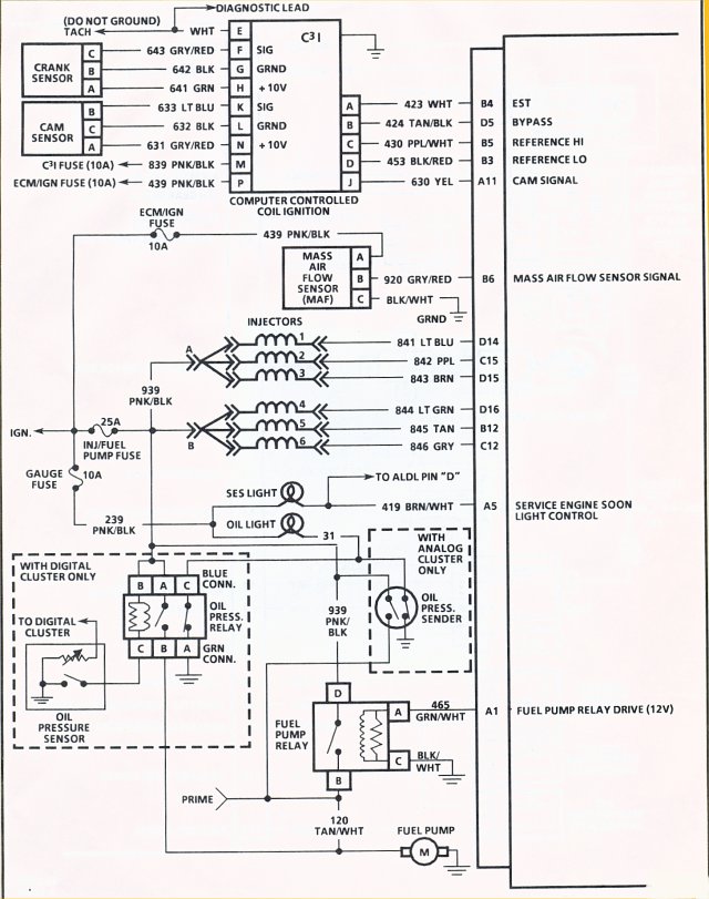
That is another thing where does the cam sensor get its power from ECM then to ICM? or ECM give power to ICM then the cam sensor gets power from there?
I might sound a little funky in the morning too early to think
The factory shop manual doesn't have a good pinout for the ignition switch. I included the above diagram in post #8 to indicate that the ignition switch powers the CCCI fuse which is where the Ignition Module gets its power from the ignition switch. I put together a chart from wiring diagrams a while back which is pasted below as well as the shop manual page indicating most of the terminals connected to the ignition switch FWIW.