Pushrod questions
- Thread starter jay dcpt
- Start date
Welcome!
By registering with us, you'll be able to discuss, share and private message with other members of our community.
SignUp Now!You are using an out of date browser. It may not display this or other websites correctly.
You should upgrade or use an alternative browser.
You should upgrade or use an alternative browser.
Bullnerd
Active Member
- Joined
- Jan 16, 2005
- Messages
- 197
With stock rockers, the fulcrum height and valve tip height is set. You measure the gap with a pushrod measuring tool, then add whatever preload you want (for hydraulic tappets) to that number.
For rockers on a threaded stud, you set the cam lobe at 1/2 lift, then set the valve open to 1/2 lift, set the rocker fulcrum-to-roller tip center square with the valve stem. Then measure with the pushrod tool and (add preload for hydraulic tappets)
Notice: I NEVER mentioned ''making the roller tip in the middle of the valve''. That has NOTHING to do with proper rocker geometry. NOTHING.
If the contact patch is too far off, you need new rockers, not wrong pushrods.
dank GN
BlackArts Automotive (661)993-8277
- Joined
- Jan 11, 2009
- Messages
- 4,039
You would know your at 1/2 the cam lift with a dial indicator. So just get a push rod checking/measuring tool and put it in bolt your rockers down and take up the slack on the push rod . I always turn the push rid till I feel a little resistance then you are at zero lash . From there you can add what ever preload you want on to the measurement. Then order push rods . Every motor I have ever built needed different push rods so there is no supplier that will know what you need till you measure it .
dank GN
BlackArts Automotive (661)993-8277
- Joined
- Jan 11, 2009
- Messages
- 4,039
No I always measure from the base circle . I’ve never done the 1/2 lift thingSo you always measure at 1/2 cam lift? Never off of base circle?
Setting up valve trains using mid=lift geometry is how you do it if you want it done right with minimal parasitic loss and the most accurate transfer of camshaft ''info''.
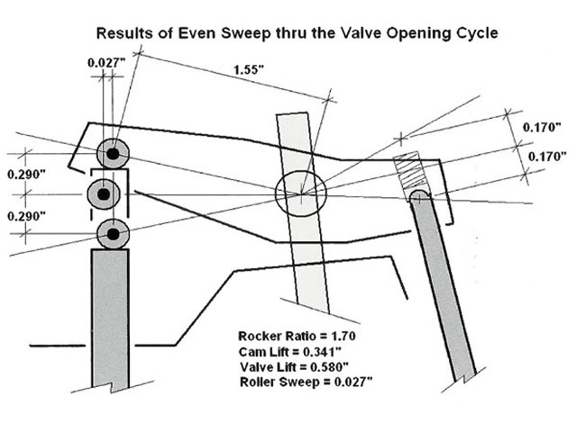
The reason you use mid lift is because it's the only way to minimize the angularity of the rocker wiping across the valve stem instead of pushing straight down on it. It also influences the speed the valve and spring is traveling. It causes it to travel fastest in the middle of travel and the slowest at dwell during ma lift, and closes the valve on the seat slower.
On a non adjustable stock Buick setup, it's more work to do it right. I had to put my heads on a milling machine and lower the stands. The other option is making the valve taller with last caps.
With threaded studs, ti's easy to do it right. You just have to know to do it.
...and once again, putting the contact patch in the middle of the valve stem is NOT the right way to do it.
- Joined
- Sep 21, 2018
- Messages
- 2,777
following
dank GN
BlackArts Automotive (661)993-8277
- Joined
- Jan 11, 2009
- Messages
- 4,039
Some good info from T&D

I might not have did you any favors... It takes a LOT of reading time to wrap your head around it.
Once the light bulb finally goes off, you'll be like ''It's so obvious now. A 5 year old should know this''. until then, it's going to be a lot of data that isn't absorbed easily through text.
Once the light bulb finally goes off, you'll be like ''It's so obvious now. A 5 year old should know this''. until then, it's going to be a lot of data that isn't absorbed easily through text.
Some good info from T&D
View attachment 343964
That is interesting. It's wrong too.
The Third sentence nailed it. You want the angle on the seat pointing up to equal the angle pointing down over the nose. (AKA 'mid-lift' geometry). Then they shot themselves in the foot talking about roller tip to stem location.
That 'info' is a little overly simplistic. With a fixed stem height and a fixed fulcrum height, the ONLY way to have proper geometry is with one single lift amount. When a cam goes bigger, the angle on the seat will stay the same but the downward angle will increase downward. The more the rocker rotates, the more it wipes across the stem instead of pushing down on it.
The only way to counter act that, is to lower the rockers pivot point so that the 'at rest' angle is steeper.

Note: For those that don't understand, a ''bigger cam'', does not have a taller lobe. It has a smaller base circle. All cams have the top of the lobe in the same place (just a hair shorter than the cam bearing journal). The bigger the cam, the more the tappet drops down in the the lifter bore.
That's why you ALWAYS have to measure for pushrod length when installing a cam. There's just too many variables to have a 'one size fits all' length. It's made even worse with a non adjustable fulcrum point.
"More Boost"
Major Member
- Joined
- Feb 13, 2005
- Messages
- 522
Learn something everyday......smh
Similar threads
Online statistics
- Members online
- 22
- Guests online
- 4,789
- Total visitors
- 4,811
Totals may include hidden visitors.