Big Dawg
Active Member
- Joined
- Aug 2, 2020
- Messages
- 136
By registering with us, you'll be able to discuss, share and private message with other members of our community.
SignUp Now!Yes correct, doubt its the pigtail though. Keep it removed and powered on the blue wire.
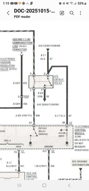
I was mistaken saying this signal goes back into the dash area, it goes out of the light blue wire on the pressure switch connector over to the passenger fenderwell area to the left of the blower motor into a 4 cavity connector that corrodes often. I have pictured the 1987 page for the 1986 climate control but that 4 pin connector is in the same place. Should have blue wires on both sides in cavity A. Try the wiggle test to see if works if not put a meter on both sides of the blue wire to see if you have voltage when A/C is selected and the pressure switch in place, or you power the blue wire at the pressure switch unplugged.
That would be C497 from the wiring diagram. It needs to pass the signal through the connector to the relay.
View attachment 408291
Okay I will tackle this tmrw.....baseball is starting!! LolOut of the relay the light blue wire for compressor control power goes from the relay to C497 cavity A blue wire, to the other side of the connector also a blue wire directly to the pressure switch. If you put power on the blue wire at the pressure switch unplugged it needs to read +12 to a good ground on both sides of that connector C497. I would unplug it and if you get voltage on one side of the connector make sure it sends +12 out of the other side of the connector. Forget the relay wires other than the light blue forget the ECM etc. Blue wire from the pressure switch needs to pass power through that connector blue wire to the relay blue. Simple tests.
Check the crimps and the contacts on the connector for the light blue wire.
Okay sounds good.....very clear. Thank youThe second blue wire does send +12 to the ECM and it gets it from the pressure switch that "should" power the compressor.
The easiest test would be to unplug the pressure switch put +12 on the blue wire in the socket from the battery, leave the key OFF and make sure that +12 goes through C497 blue wire to the relay blue wire. Use a meter at each location, black probe on a good ground, and find where the +12 disappears on each blue wire in the circuit including crimps and the contacts in C497. No harm to the system if the pressure switch is unplugged.
To power the blue wire just strip some 18 gauge wire and inch, fold it in half and shove it into the rubber connector socket, unplugged, with the other end going to the battery.
Okay so I just finished checking everything as the suggested above and the blue wire from the AC Pressure switch connector (disconnected) with 12v directly from the battery shows 12v at the c497 blue terminal and also at the Relay connector.The second blue wire does send +12 to the ECM and it gets it from the pressure switch that "should" power the compressor.
The easiest test would be to unplug the pressure switch put +12 on the blue wire in the socket from the battery, leave the key OFF and make sure that +12 goes through C497 blue wire to the relay blue wire. Use a meter at each location, black probe on a good ground, and find where the +12 disappears on each blue wire in the circuit including crimps and the contacts in C497. No harm to the system if the pressure switch is unplugged.
To power the blue wire just strip some 18 gauge wire and inch, fold it in half and shove it into the rubber connector socket, unplugged, with the other end going to the battery.
Disregard this...12v show up at green/yellow wire when the car is actually running. I was checking earlier with the ignition in the run position.This is strange.....now my green and yellow wire(A2) isn't getting 12v at all to the relay.
I used my hood light...it didn't turn on at all. Crazy..it is only 3 months old from Caspers.This is what I use for a test lamp that draws some current.
View attachment 408299
Update:Need to check the light green wire at the pressure switch for +12 when A/C is selected.
Sounds to me like the blower and A/C clutch control module is shot not sending enough current out to engage the clutch.
If you don't get +12 at the relay blue wires with the system engaged, and as you found the wiring is good, the control module can't provide enough current to turn on the clutch.
I would get a trunk light bulb which draws about one ampere of current, put two wires on it by soldering or use clip leads, one lead to battery ground, the other lead to the light green wire on the pressure switch disconnected and see if it lights up when the system is properly set to turn on the A/C.
If the bulb won't light up brightly I would say the control module is shot.
Testing with a meter doesn't draw the kind of current the clutch would as a voltmeter is designed to be non-invasive testing (no load on the system) but the lamp test at the pressure switch will draw some current and if it doesn't light and the light green wire reads low volts the clutch control module is bad.
If you have a working hood lamp, make sure it lights up with the hood open, leave the hood open, disconnect the little connector near the wiper motor and put a stripped wire into the lamp connector and the other end into the green wire contact on the pressure switch and try the A/C. Same as sourcing a test bulb assuming the hood lamp always works right.