You can type here any text you want

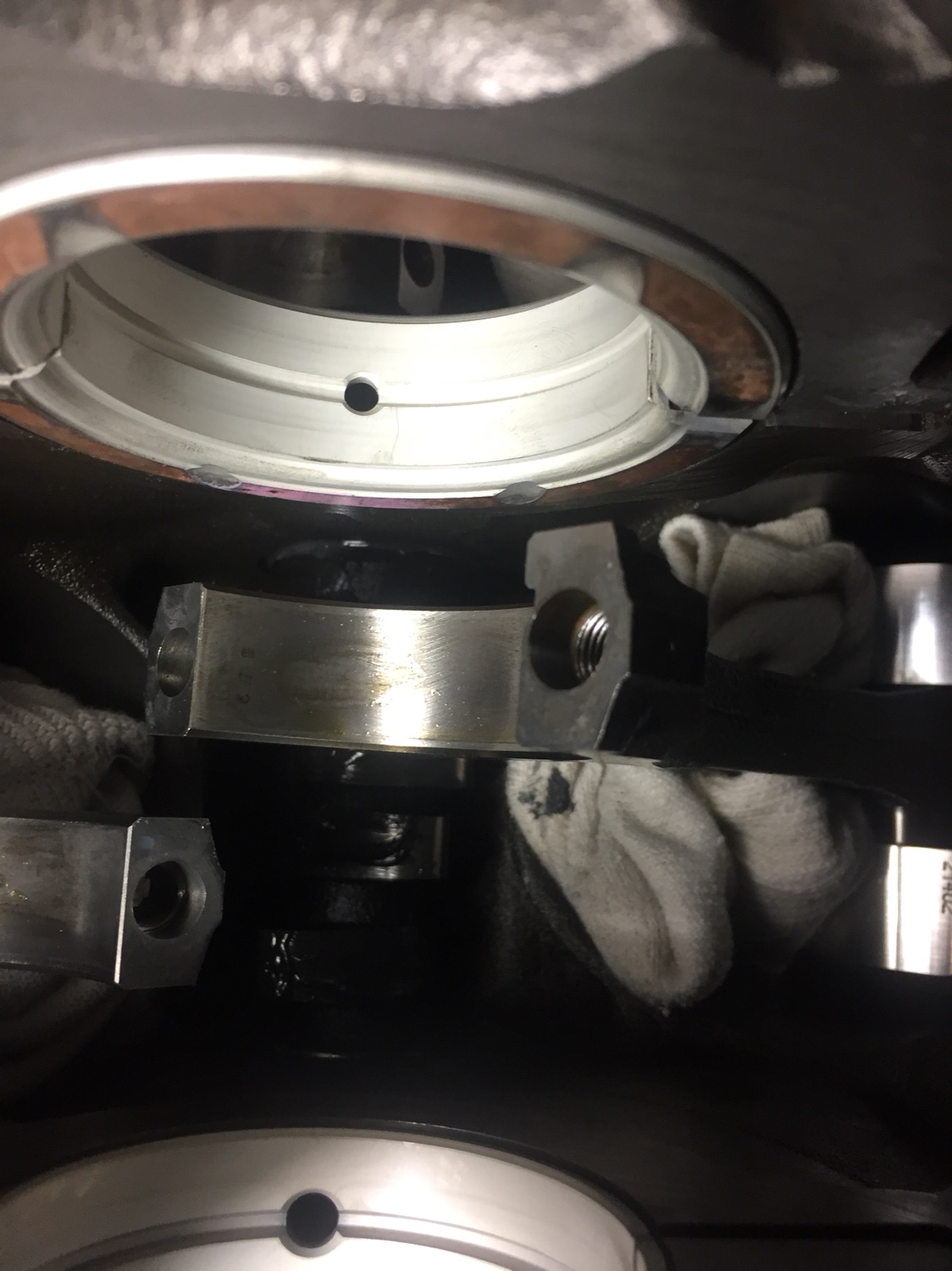
Clevite MS-960P oil feed holes

Welcome!

By registering with us, you'll be able to discuss, share and private message with other members of our community.

SignUp Now!

Drewster

Wish I Had A Clone. AKA Andrew Youlio
Joined
May 31, 2001
Messages
787
I’m thinking the #2 oil feed hole is way to small on the Clevite MS-960P set. Im planning on drilling it out to match the other holes unless someone has a good reason to leave as is. See pics, compare and comment please.
Gona go tighten caps and bore gage clearance now. Going to do new bearings and clean up crank.
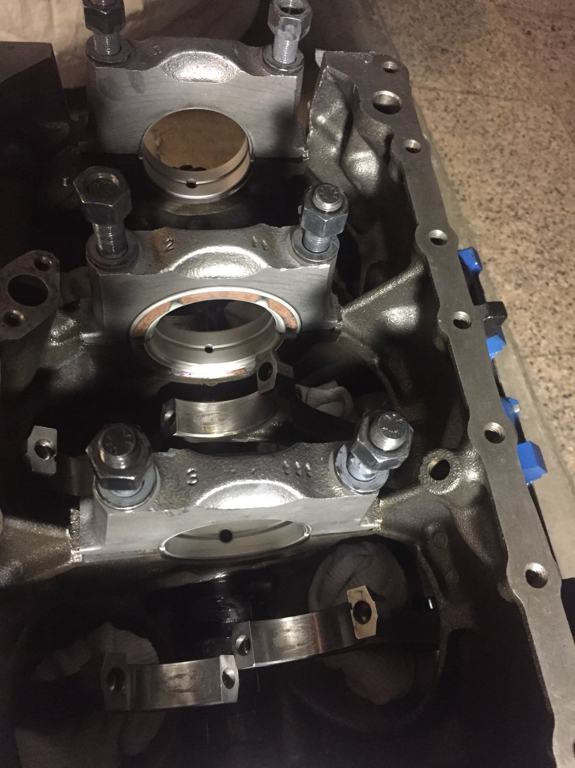
dd558fc5dd9566a514513c92440a9520.jpg
ba3750d152eee67f0f7a614ef0b2a0f0.jpg


Sent from my iPhone using Tapatalk
 
Yes just make sure it matches up with the supply hole
 
If your oil pressure is low when you fire the engine, you may regret drilling out the bearing?

Is your objective to increase flow?

If so, will you add a high oil volume pump to compensate to maintain adequate oil as velocity and pressure will be decreased?

I have seen a few blocks that had the oil holes drilled out, and were trashed since they could not develop enough oil pressure.

This guy speaks truck loads of good advice. I would go with Nick on this one.
 
I'm not sure why one bearing would have a smaller feed hole. I'd at least make #2 match the others. Also, In my opinion, if the bearing clearance is good, enlarging all the bearing holes to match the galley wouldn't be necessary. No way that oil flow around the journal could be greater than the flow through the bearing orifice unless the clearance is too loose.
 
I always match port my bearing holes to the block. The radius the trailing side so the crank can actually 'drag' the oil into the journal area.


I'm less worried about the oil pressure in the gallery, and more worried about letting the oil get onto the bearing areas where I need it.
 
Just like what Rreedogg posted. The #2 was the only hole I have concerns about. It’s really small. Smaller than the others in the set and smaller than Speedpro FM107 #2.
I’m not running a high flow pump or loose clearances. Just had concerns of starving the #2 bearing. So that was the only feed hole I thought needing enlarging to match the others.
I thought there may have been some engineering finding that smaller was needed on #2. Or maybe it’s just the way Clevite mix and match shells to make a set.
Also saw the #4 groove is only bout 70% of the upper shell. Will post pic of that soon.
I like the idea of the additional chamfer on trailing edge side of hole.


Sent from my iPhone using Tapatalk
 
The oiling hole diameter should be the same as the others. Nothing special about the #2 galley except that it's a thrust bearing, which to me increases its need for oil. There's some discussion about it here: https://www.turbobuicks.com/forums/buick-v6-turbo-tech/34061-main-bearing-modifications.html

I don't think anyone really knows which is the oil flow bottleneck, the oiling hole or the journal clearance. I suspect that's why the old Buick books recommend opening up all the passages, just for insurance against the unknown. To me, it's better to let the journal clearance be the largest restriction to oil flow and make sure there is no restriction upstream (galley diameter or oiling hole diameter). This ensures the bearing is not starved. But, like others said, these engines live a long time in stock form. Perhaps the oiling holes are large enough as-is.
 
I don't think anyone really knows which is the oil flow bottleneck, the oiling hole or the journal clearance. I suspect that's why the old Buick books recommend opening up all the passages


Surely I'm not the only one that's done the basic math on the cross section area.

It's just Pi R squared.
 
No, it's pretty simple. It's the size of the crank journal minus the size of the bearing ID (X2) for the cross section area of the bleed area. If you really want to get specific, you need to know the total bleed area of the crank journal plus the bleed area of the rod(s) journal too.


Keep in mind lubrication is NOT relative to pressure, it's a function of flow. Getting rid of anything that might impede flow will NEVER hurt and might help.

Sounds like free stuff to me.
 
The area of the journal clearance is only part of the equation. The distance the oil has to travel through that area lowers the flow rate.

I agree, removing all restriction to flow is bonus.
 
For example: a 10 foot hose flows more than a 20 foot hose with the same inlet pressure.

Drewster, sorry to stray off topic. If you haven't already, I say make all the bearing oil supply holes match.
 
Match main bearing oil feed hole to the hole in journal. The clearance of the bearings circular "squish" when the caps are torqued vs cranks main journal and the leak of the oils hydrodynamic wedge of the said difference. So yes make the hole in the bearing the size of the feed hole in block.

The the total loss in psi through the oiling system is all the leaks taking away from the oil supply from pump at rpm up to the relief psi. What leaks out of all the bearings...production isnt priority main...out of oil pump to cam bearings/cross over to lifter galleys ....then to mains, rods, etc. All of the bearings are in a psi'd wedge of oil and said wedge leaks.
 
Back
Top