You can type here any text you want

Motion Raceworks 2 Stage Air/Oil Separator?

Welcome!

By registering with us, you'll be able to discuss, share and private message with other members of our community.

SignUp Now!

OKTurbo

Member
Joined
May 28, 2001
Messages
620
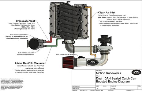
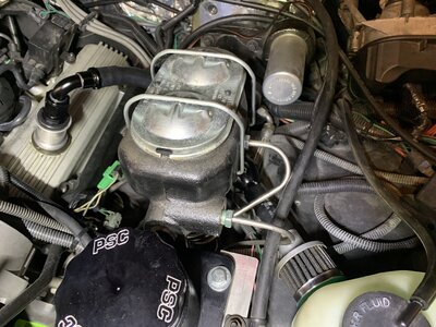
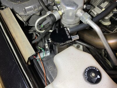
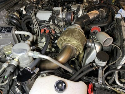
Has anyone here tried this new ‘catch tank’ from Motion? I got one for Christmas and am in the process of installing it on my 87 GN.

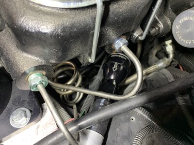
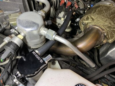
Pretty cool piece for a turbo car. The vacuum port has a built in check vale that closes under boost but still pulls thru the PCV valve under vacuum. The filtered vent stays closed but will open when the crankcase goes positive (pressure).

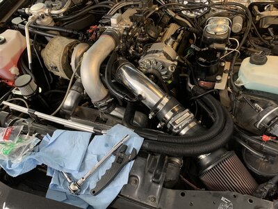
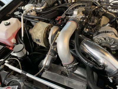
I’ve ordered a new MAF pipe from earlbrown, but it hasn’t arrived yet. I’ll be adding a filtered air port to the passenger valve cover similar to the factory set-up when the MAF pipe gets here..

Curious if any other Turbo Buick guys or gals have looked at this option for our cars.
IMG_5985.jpeg
IMG_5987.jpeg
IMG_5991.jpeg
 
I'm currently designing a similar set up with a Mighty Mouse catch can. I'll post some pictures when I have more to show.
 
Has anyone here tried this new ‘catch tank’ from Motion? I got one for Christmas and am in the process of installing it on my 87 GN.

Pretty cool piece for a turbo car. The vacuum port has a built in check vale that closes under boost but still pulls thru the PCV valve under vacuum. The filtered vent stays closed but will open when the crankcase goes positive (pressure).

I’ve ordered a new MAF pipe from earlbrown, but it hasn’t arrived yet. I’ll be adding a filtered air port to the passenger valve cover similar to the factory set-up when the MAF pipe gets here..

Curious if any other Turbo Buick guys or gals have looked at this option for our cars.
View attachment 403572View attachment 403573View attachment 403574
got a link to catch can?
 
Update on the ‘clean air’ side of the Pcv. I’m using the original passenger side valve cover breather and running AN10 fittings and 5/8 hose to the elbow right after the MAF. Still need to mount the elbow and check valve to the MAF end of the hose. Check valve will prevent flow from VC back into the inlet.
IMG_6021.jpeg

IMG_6022.jpeg

IMG_6023.jpeg

IMG_6019.jpeg
 
We both have similar ideas here but there's a few things to think about.

It looks like your intake PCV port is still running into the vacuum block on the TB vs the can correct?

The best way to draw from the crankcase would be the PCV port or the mechanical fuel pump block off location at the front of engine (I didn't go this route).

The valve cover port you are using for the catch can was originally designed to get suction (vacuum) from the turbo to pull some of the crankcase pressure out of the engine under boost. But this location is at the end of the chain vs the intake access to the crankcase and the VC port made the turbo compressor and intercooler load up with oil film.

If your main goal is to pull pressure out of the crankcase during WOT your current setup, as I understand it, will draw in at WOT from the can filter and possible reduce vacuum draw. I'd assume a closed can would be more ideal and then use the can to be the air/oil separator.

I went, PCV port on intake mani, no PCV valve into closed catch can, then catch can out into inlet pipe port. It's not a lot of suction at WOT but enough to aid in the crankcase pressure to follow that path and then the VC breathers take care of the rest.
Poor man's vacuum pump similar to the factory but with a catch can vs the turbo compressor getting oil film from passenger valve cover.

Hope that helps and I didn't misunderstand your intention for the can.
 
The valve cover port on the passenger side is going to the MAF inlet tube. The air/oil separator catch can is between the Pcv valve under the intake and the vacuum block on top.

This is a street car…cruise nights etc. I wanted a system that will keep the oil clean when putting on street miles. The can has a built in check valve on the vacuum side. It also has a normally closed pressure relief valve under the filter vent. Stock PCV valve is metered for the ‘correct’ flow to evacuate the crankcase at idle and at cruise. Can removes the moisture/oil vapor going to the vacuum block on the intake…hopefully keepin oil out of intake.

Driver’s side valve cover has the original sealed fill cap. Passenger side valve cover supplies fresh, metered air to the crankcase.

When under boost, the catch can check valve closes. If/when pressure builds up in the crank case it will vent out the can’s relief valve and filter.

That’s the plan. Here’s a simple sketch. Should work, right?
IMG_0406.jpeg
 
Not sure you will get enough venting crank case pressure through the pcv. You could add a vent in the drivers side cover to help.
 
Ah I see now, it'll work that way too. Your setup is better than just blocking off pass VC port and at WOT the breathers having to expel the gasses. Your passenger VC getting the draw from the inlet pipe 2" vacuum will help.
 
not sure about the PVC are you going to the PVC in the intake?
It should go directly to Vacuum you need to revisit the boosted instructions
 
not sure about the PVC are you going to the PVC in the intake?
It should go directly to Vacuum you need to revisit the boosted instructions
PCV in the bottom of the intake manifold is routed thru the air/oil separator can then back to the vacuum block on top of the intake dog house. Vacuum pulls thru the stock Pcv valve. Separator can removes the vapor before it goes into the vacuum block.
 
Not sure you will get enough venting crank case pressure through the pcv. You could add a vent in the drivers side cover to help.
You got me thinking about that Pronto. The stock PCV may not flow enough at full boost. I think I’m going to vent the driver’s side valve cover with the check valve to prevent sucking in at idle/cruise but allow it to blow out when needed. I’ll use the old filter vent at the end of the hose.

I’m not going to put a check valve on the PS VC to MAF hose…just like the factory had it. It can draw filtered/metered air when needed or vent back to MAF if needed. Turbo may provide enough ‘suck’ when at full boost to vent the crankcase. The passenger VC is baffled and I’m still using the factory filtered vent fitting…should prevent oil from getting into the turbo inlet.

I’ll take some pics when I get it plumbed up. Might be a few days. It’s 14degF out there now.

The point behind all this it to prevent un-metered air getting in at idle (high idle BLM’s) yet still have positive ventilation to keep condensate/combustion junk out of the oil. Still need the system to vent blow-by when in boost.
 
Guys, your over thinking. Don't reinvent what they already laid out for you. The top of the Can says VAC (this should go to your PCV) and the other says Crank (this should go to either side of your valve cover, preferably the passenger side on a Turbo Buick). The final hose will go from your drivers side valve cover to the turbo inlet pipe.
 

Attachments

  • Screenshot 2025-01-19 113343.png
    Screenshot 2025-01-19 113343.png
    420.4 KB · Views: 34
I have the Racetronix version which is nice but I would rather of bought the Motion Works can. Although the Racetronix version is routed the same way I don't think it's technically a 2 Stage Vac setup. I'm sure it doesn't have the baffling and built in check-valves like the Motion Works.
 
The MM has baffling and a boost check valve too. I like not having to add a check valve in the line.
 
Update with some picture. Driver’s side valve cover now has 10AN hose going to check valve and filter/vent. The check valve allows pressure to escape but blocks airflow back into the valve cover/crankcase.

I mounted a closed/flow thru separator can for the ‘clean air’ side of the Pcv system. When vacuum is present at idle/light cruise air is drawn into the valve cover (post MAF so the air is metered…solve high idle BLM’s?). Under boost if there is enough negative pressure in the MAF pipe it can draw from the VC thru the can to help keep oil out of the turbo inlet. Still need to figure out how I’m going to route that line.
 

Attachments

  • IMG_6032.jpeg
    IMG_6032.jpeg
    2.6 MB · Views: 10
  • IMG_6033.jpeg
    IMG_6033.jpeg
    2.3 MB · Views: 9
  • IMG_6034.jpeg
    IMG_6034.jpeg
    2.7 MB · Views: 9
  • IMG_6036.jpeg
    IMG_6036.jpeg
    2.5 MB · Views: 10
  • IMG_6035.jpeg
    IMG_6035.jpeg
    2.6 MB · Views: 10
Back
Top