Building a 1964 Buick Special

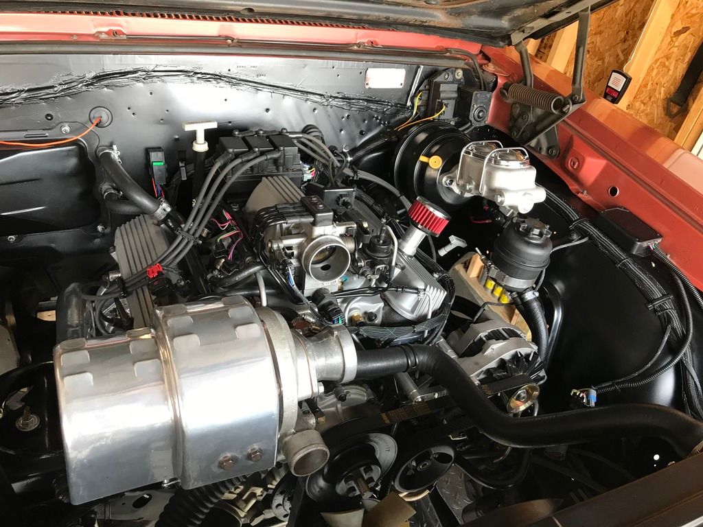
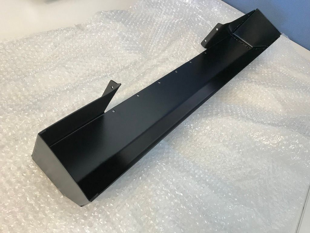
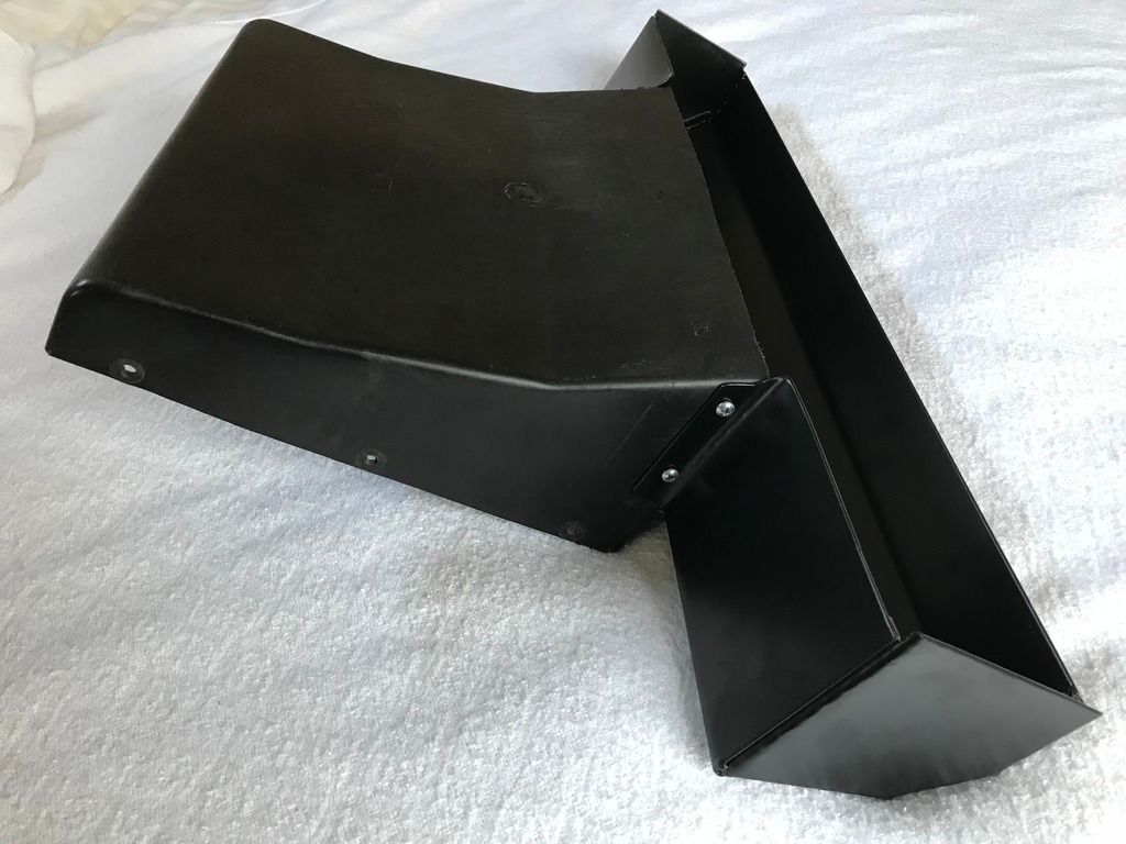
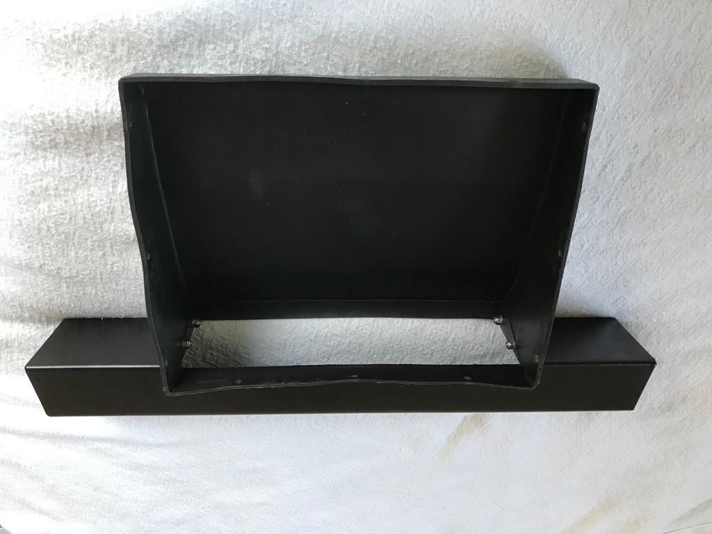
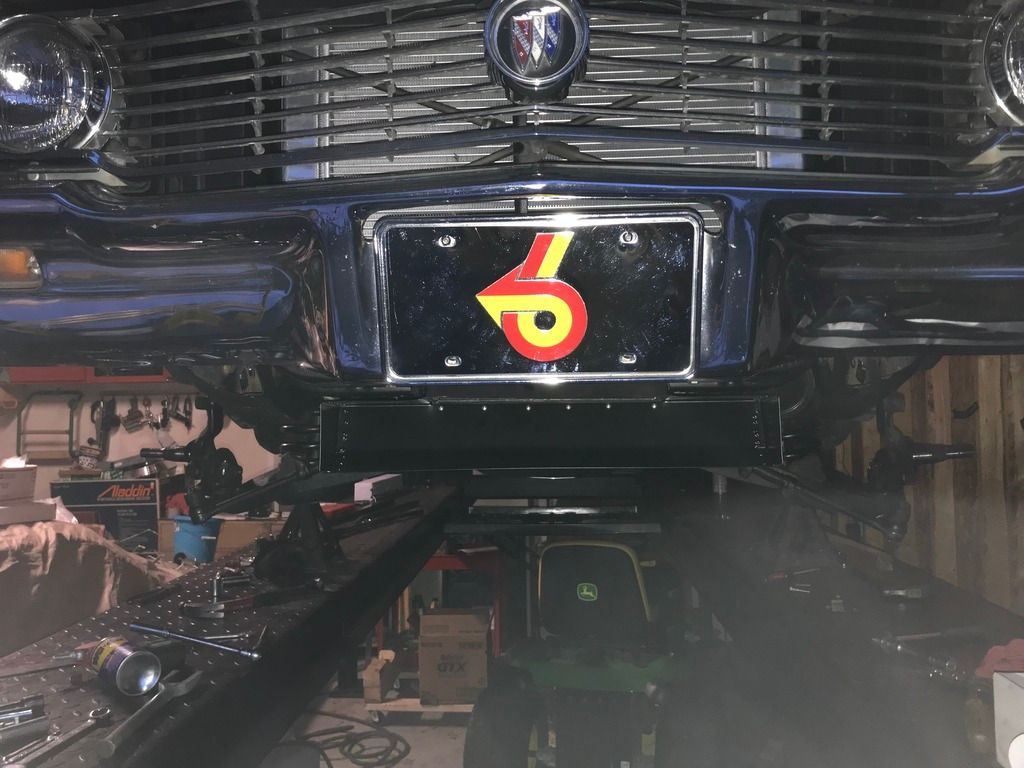
I wasn't very happy with the intercooler scoop. Seemed to hang too low, and was very visible under the front end of the car.

5CB20B3C-641B-468D-AB98-1FAF9FC95DA4_zpsk6tdqqwh.jpg


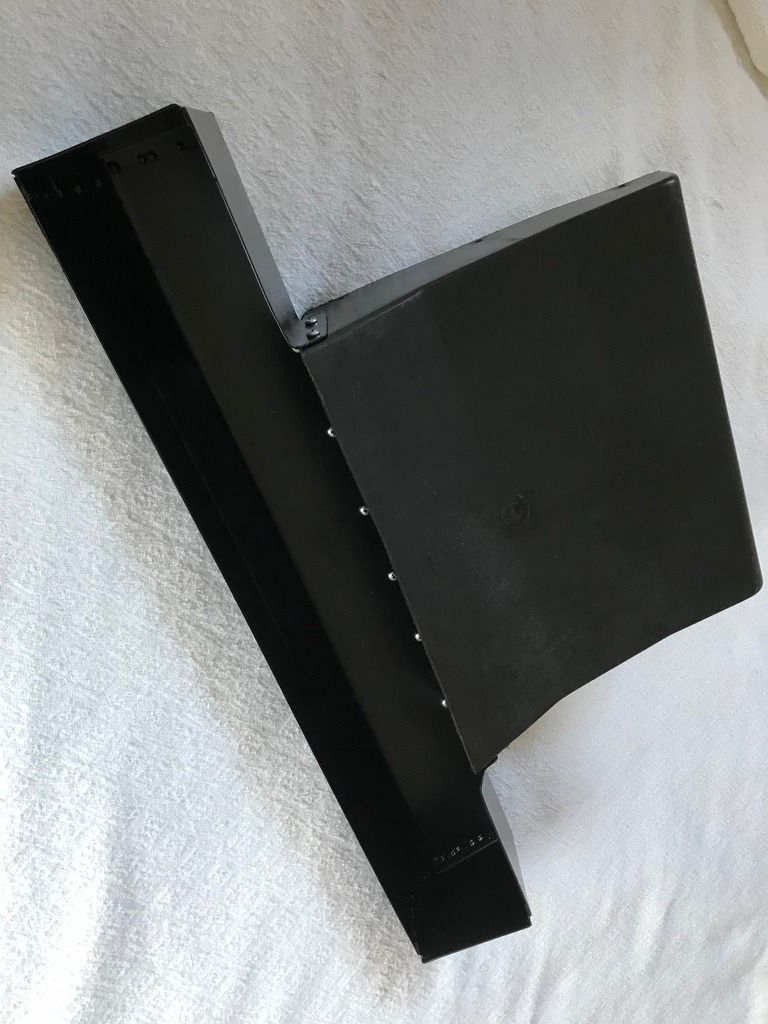
I started mocking up a reworked scoop. The lower section was trimmed away, and I shortened and widened the intake area. I used the old opening as a guide and kept the same sectional area. A little cardboard was used to make a template.

IMG_4341_zps9kt9igs6.jpg


IMG_4340_zpszxnfywbl.jpg


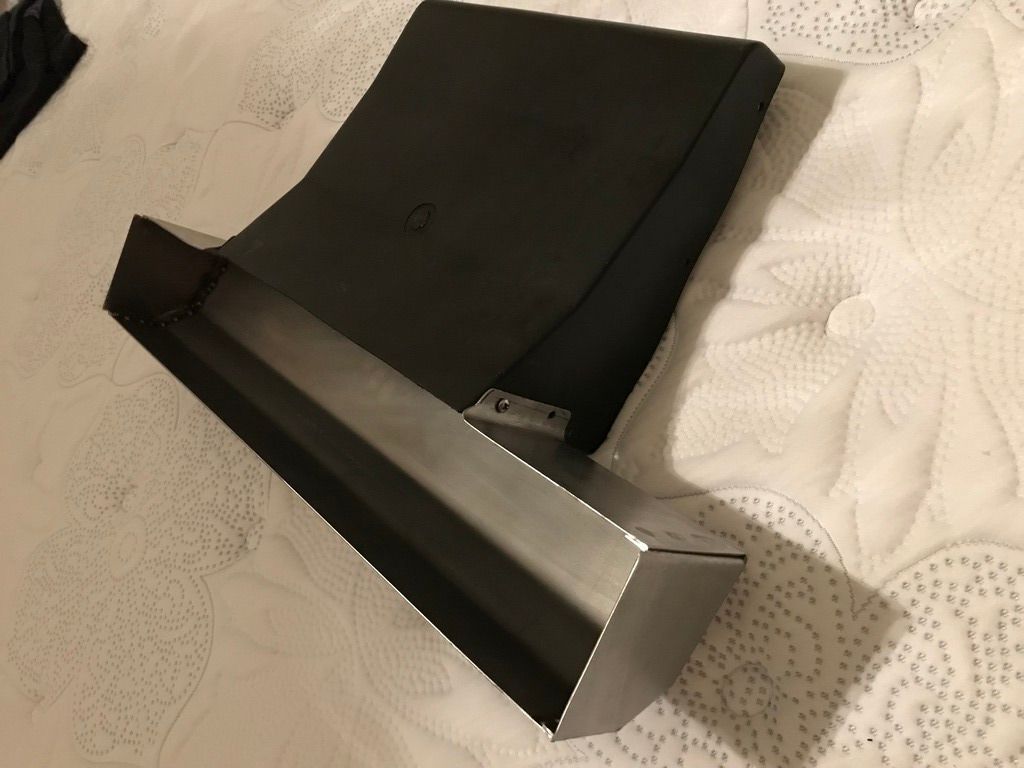
Finally, the template was transferred to sheet metal and bent/fabricated on a shear and rake. Came out pretty good!

IMG_4345_zps6dmnaywr.jpg


IMG_4351_zpsg1cxvyrz.jpg


IMG_4353_zps6l4zgyhp.jpg
 
This weekend was pretty nice weather here in MI, so I got my master cylinder and booster installed. It's a pretty tight fit between the factory power junction block and steering reservoir, so I'll have to get creative with the line routing down to the prop valve. It does look right at home and matches the theme pretty well.

IMG_4394_zpsrgiyqrlw.jpg
 
I spent this weekend creating some brake lines. Although I purchased a ready-made set from Inline Tube, there were too many obstacles in the way to use the kit. Things like the power steering reservoir, positive power junction block on the driver's side fender, and unusual exhaust routing (compared to a stock '64 V6) made most of the lines unusable.

So I had to fab a lot of lines from auto parts store grade straight line. I started with straight line to make a pattern, and made markings every inch along the length. I then used a compact bender and a tape measure to start fabbing the line.

IMG_4421_zpst56x7gqo.jpg


I then completed the pattern and test fit to make sure everything clears.

IMG_4422_zpskkonptwg.jpg


Then I used the markings to determine how long the new line needed to be, and measured it out/cut from a virgin line. By doing this, I could keep one "factory" flare, and only needed to flare one end - which reduces the likelihood of leaks from a bad flare. The prop valve will mount on the frame behind the upper control arm, and the lines attach on the inboard side of the master cylinder instead of the traditional outboard side. Came out pretty good!

IMG_4424_zpskimxth1e.jpg
 
The powder coating is done on the intake tubes and the lower scoop. The photo of the intake tube isn't great, but it's a pretty close match to the intake and valve covers.

IMG_4430_zpsdlxlq75y.jpg


IMG_4429_zpskrzpmaol.jpg


Assembling the scoop to the intercooler shroud shows a nice match. Can't wait to get this installed, but it will have to wait until the brakes are installed because I want to make sure I have plenty of room to work in front of the engine.

IMG_4431_zpsytog1n5r.jpg


IMG_4432_zpssassusbo.jpg


IMG_4434_zpstmilgj18.jpg
 
It's a little dark outside, but here's a shot of the test fitment of the intercooler scoop. It's much tighter to the bottom of the core support, plus it's the same width as the support, which makes it look more like it was made for this chassis.

IMG_4435_zpsxkigmhya.jpg
 
Top