Follow my port and polish project
- Thread starter DougsfastZ
- Start date
Welcome!
By registering with us, you'll be able to discuss, share and private message with other members of our community.
SignUp Now!You are using an out of date browser. It may not display this or other websites correctly.
You should upgrade or use an alternative browser.
You should upgrade or use an alternative browser.
DougsfastZ
4.1
- Joined
- Jan 30, 2004
- Messages
- 727
Thanks disco, I'll see if I can get beads locally.
Should be easy. I got some at a local welding joint/tool and I live in a town where I can't get jack sh!t locally I need. But I glass bead all my alum stuff. Sand is too rough. Even on steel in most cases. Do you have a cabinet? Might be kinda pricey with an open blaster. I paid 30 bucks for a 50 pound bag.
I bet soda would work good too. You need a specific outfit for that though. I might have to try out some cast aluminum with mine and see how it goes.
I bet soda would work good too. You need a specific outfit for that though. I might have to try out some cast aluminum with mine and see how it goes.
challengermike
Member
- Joined
- Nov 14, 2005
- Messages
- 717

DougsfastZ
4.1
- Joined
- Jan 30, 2004
- Messages
- 727
So tonight, I started the actual porting and polishing. I decided to start with the turbo compressor housing to learn on since it was the easiest to do, and fairly cheap to replace if I messed up.
I set up an old patio table on the side of the house, over the grass, so I didn't have to clean up metal shavings. I used my 24" industrial fan to keep the shavings off of me and to stay cool. I also ran two air lines to the table, one for the die grinder, and the other for the air blow gun.
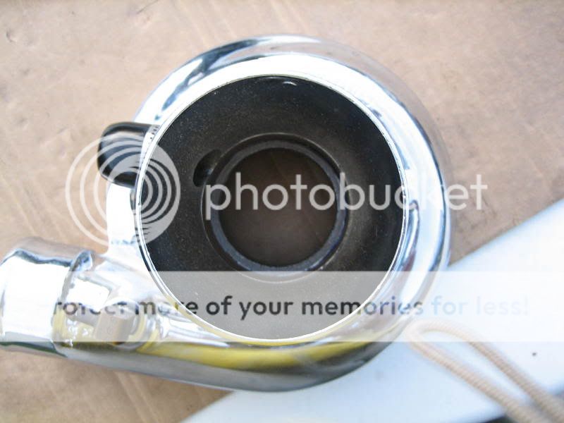
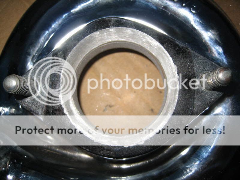
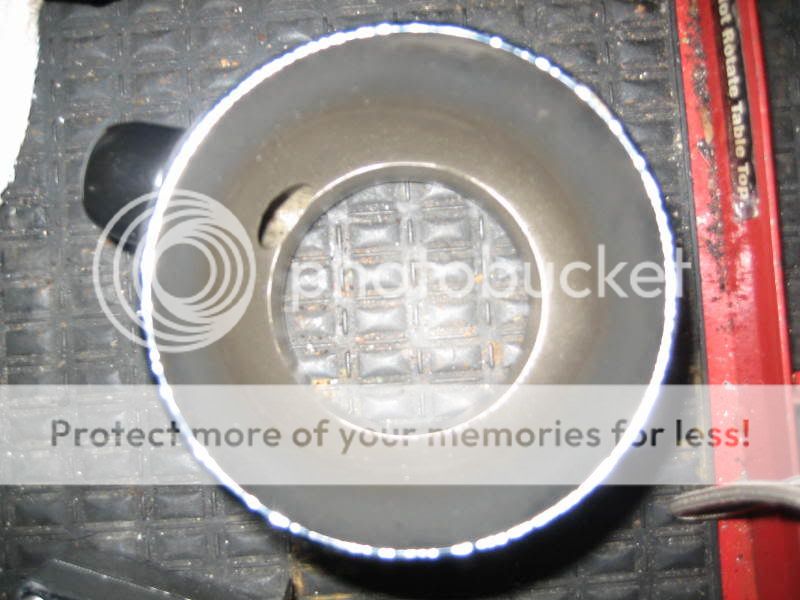
Here is a picture of the stock turbo compressor housing. I did take off some material a few months back, to test the sanding drums, so I don't have any pictures of the housing in complete stock form. As you can see, I marked the housing with a large permanent marker, and scribed a line to keep and eye on how much material to remove. I simply used the stock inlet bell and a dental tool to make the line.
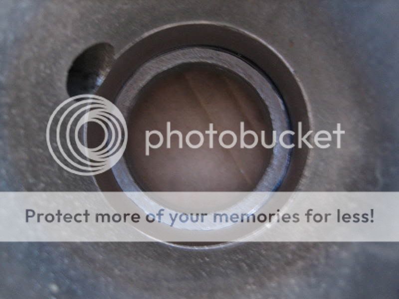
This is what the housing looked like after I used the 6" aluminum carbide burr. It's takes off material in a small divots, and leaves it very rough. Notice I left some of the scribe line in tact, this was done so I can use the sanding drums to to take it to the line. You'll also see some chipping on the housing face, this is because the housing is chrome, and that is simply the chrome chipping off.
This is the same picture, just with the bell in place. You can now see there is still some material to remove with the sanding drums. I was trying to be conservative with the burr to really understand how much material it removes.
Another shot of the bell installed.
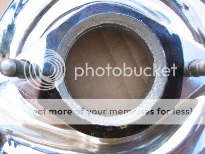
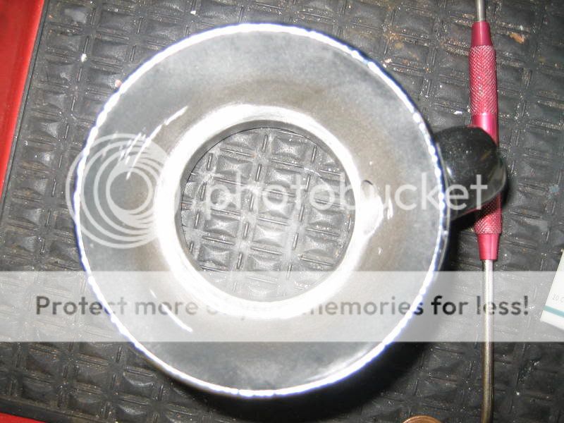
At this point, I've used the large diameter, 40 grit sanding drum, to remove the divots, and port the opening to the scribed line. Notice the line is now gone.
Similar picture with the bell installed, notice there is no more ridge.
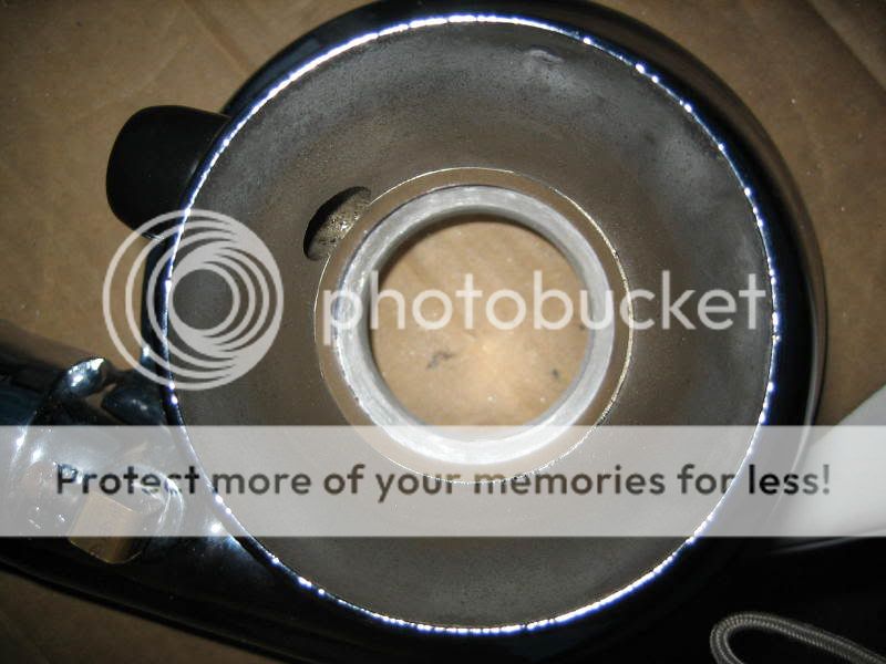
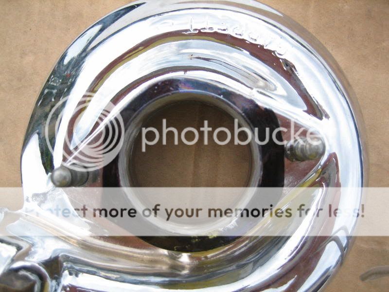
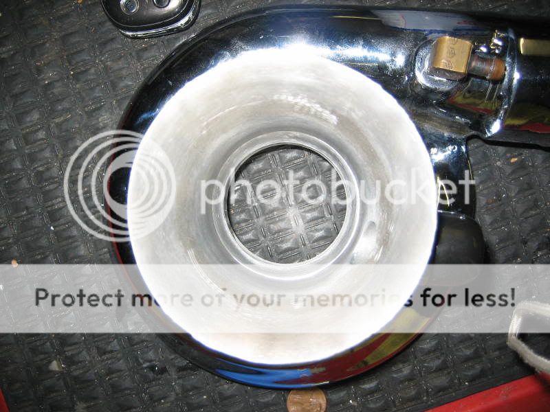
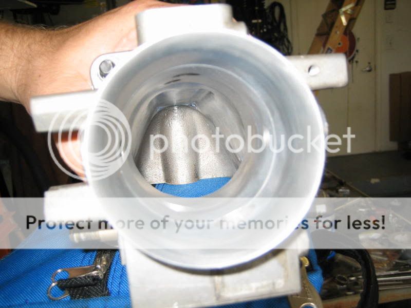
The next step was to use the large diameter, 80 grit, sanding drum to take out all the deep scratches from the 40 grit drum. Then I used the blue scotch brite cross buff, finally followed by the red scotch brite cross buff. This is the results:
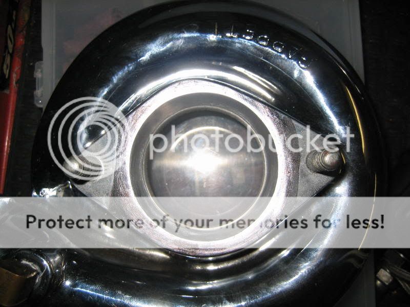
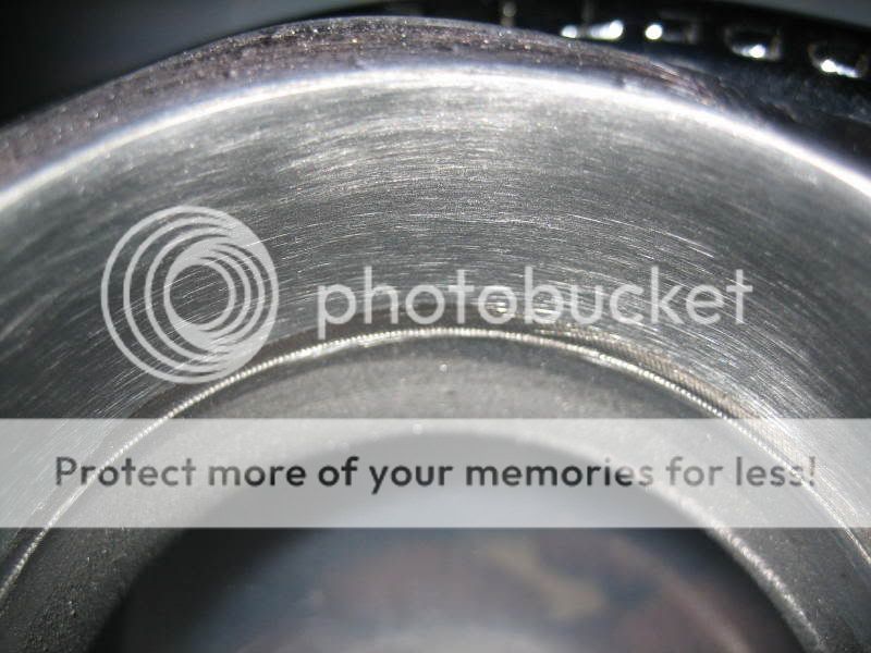
Close up picture of the final results. I should of spent more time with the 80 grit drum and the cross buffs, but it is very smooth to the touch. The pictures shows good details, but makes it look rougher than it is. Also note, the small line that I ported too, that is very close the compressor wheel, and it worked well as a "no port zone" marking.
Continued...........
I set up an old patio table on the side of the house, over the grass, so I didn't have to clean up metal shavings. I used my 24" industrial fan to keep the shavings off of me and to stay cool. I also ran two air lines to the table, one for the die grinder, and the other for the air blow gun.
Here is a picture of the stock turbo compressor housing. I did take off some material a few months back, to test the sanding drums, so I don't have any pictures of the housing in complete stock form. As you can see, I marked the housing with a large permanent marker, and scribed a line to keep and eye on how much material to remove. I simply used the stock inlet bell and a dental tool to make the line.
This is what the housing looked like after I used the 6" aluminum carbide burr. It's takes off material in a small divots, and leaves it very rough. Notice I left some of the scribe line in tact, this was done so I can use the sanding drums to to take it to the line. You'll also see some chipping on the housing face, this is because the housing is chrome, and that is simply the chrome chipping off.
This is the same picture, just with the bell in place. You can now see there is still some material to remove with the sanding drums. I was trying to be conservative with the burr to really understand how much material it removes.
Another shot of the bell installed.
At this point, I've used the large diameter, 40 grit sanding drum, to remove the divots, and port the opening to the scribed line. Notice the line is now gone.
Similar picture with the bell installed, notice there is no more ridge.
The next step was to use the large diameter, 80 grit, sanding drum to take out all the deep scratches from the 40 grit drum. Then I used the blue scotch brite cross buff, finally followed by the red scotch brite cross buff. This is the results:
Close up picture of the final results. I should of spent more time with the 80 grit drum and the cross buffs, but it is very smooth to the touch. The pictures shows good details, but makes it look rougher than it is. Also note, the small line that I ported too, that is very close the compressor wheel, and it worked well as a "no port zone" marking.
Continued...........
DougsfastZ
4.1
- Joined
- Jan 30, 2004
- Messages
- 727
On to the inlet bell.
This is a shot of the bell, which is 100% stock. Two things I focused on here. One is to take off the small ridge half way down into the bell, and two, to bellmouth the entrance of the bell even more.
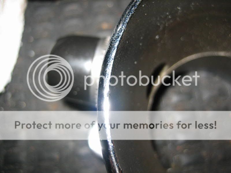
Close up shot of the thickness of the leading edge of the inlet of the bell. Plenty of material to remove.
I took the small ridge off with an 40 grit sanding roll. Here is the results:
This is the shot of the bell completed. I took the carbide burr to bellmouth the inlet opening even more, followed by 40 grit, 80 grit, and both cross buffs, for both areas.
This is a close up shot of the new leading edge of the bell. It's about as sharp as a dull lawn mower blade.

All in all, this so far took about 2 hours. Here are some tips that I learned about along the way.
- Use grinders grease! It works very well. I used it on the burrs and sanding rolls. No loading up, and the blades on the burrs are still very sharp
- Don't use a ton of RPM. I found the best cutting and sanding speed, is 1/2 throttle on the die grinder. For the cross buffs, I just cracked the throttle.
- Keep your parts clean. After every pass of a certain cutting too, I used my air gun to blow all of the fine particles away from the parts. This kept everything cleaner and allowed me to focus better on the port work.
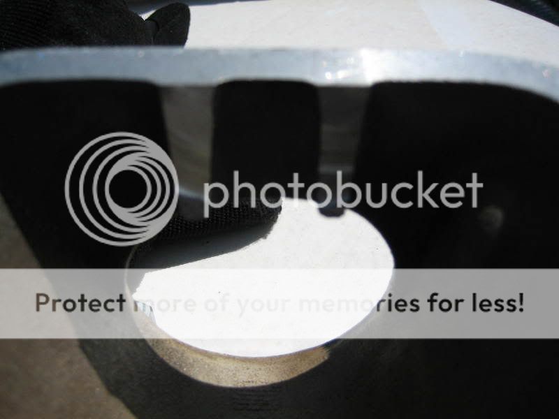
- Use gloves. The carbide burrs throw out very sharp small pieces of aluminum, and it will get in your skin. I just bought some fresh Mechanix gloves, and they protect my hands well.
- I found that after sanding down the divots with 40 grit, take about twice as much time with the 80 grit. This provided a much smoother result when done with the cross buffs.
Overall it's very easy to pick up the technique and see results. I'm happy with what I've done so far and look forward to porting the other parts.
Tomorrow I plan on working on the turbo outlet and intercooler inlet.
This is a shot of the bell, which is 100% stock. Two things I focused on here. One is to take off the small ridge half way down into the bell, and two, to bellmouth the entrance of the bell even more.
Close up shot of the thickness of the leading edge of the inlet of the bell. Plenty of material to remove.
I took the small ridge off with an 40 grit sanding roll. Here is the results:
This is the shot of the bell completed. I took the carbide burr to bellmouth the inlet opening even more, followed by 40 grit, 80 grit, and both cross buffs, for both areas.
This is a close up shot of the new leading edge of the bell. It's about as sharp as a dull lawn mower blade.
All in all, this so far took about 2 hours. Here are some tips that I learned about along the way.
- Use grinders grease! It works very well. I used it on the burrs and sanding rolls. No loading up, and the blades on the burrs are still very sharp
- Don't use a ton of RPM. I found the best cutting and sanding speed, is 1/2 throttle on the die grinder. For the cross buffs, I just cracked the throttle.
- Keep your parts clean. After every pass of a certain cutting too, I used my air gun to blow all of the fine particles away from the parts. This kept everything cleaner and allowed me to focus better on the port work.
- Use gloves. The carbide burrs throw out very sharp small pieces of aluminum, and it will get in your skin. I just bought some fresh Mechanix gloves, and they protect my hands well.
- I found that after sanding down the divots with 40 grit, take about twice as much time with the 80 grit. This provided a much smoother result when done with the cross buffs.
Overall it's very easy to pick up the technique and see results. I'm happy with what I've done so far and look forward to porting the other parts.
Tomorrow I plan on working on the turbo outlet and intercooler inlet.
DougsfastZ
4.1
- Joined
- Jan 30, 2004
- Messages
- 727
Tonight I worked on the turbo outlet and the intercooler inlet. I used the same process as I did with the turbo inlet and bell, but I added a polishing step. I found it difficult to polish the metal after the 80 grit sanding roll, so after using the 80 grit, I used a 120 grit flapper sanding wheel that came with the SA port and polish kit. It helped take out the scratches and allowed me to use the scotch brite buffs less to get a nice polish.
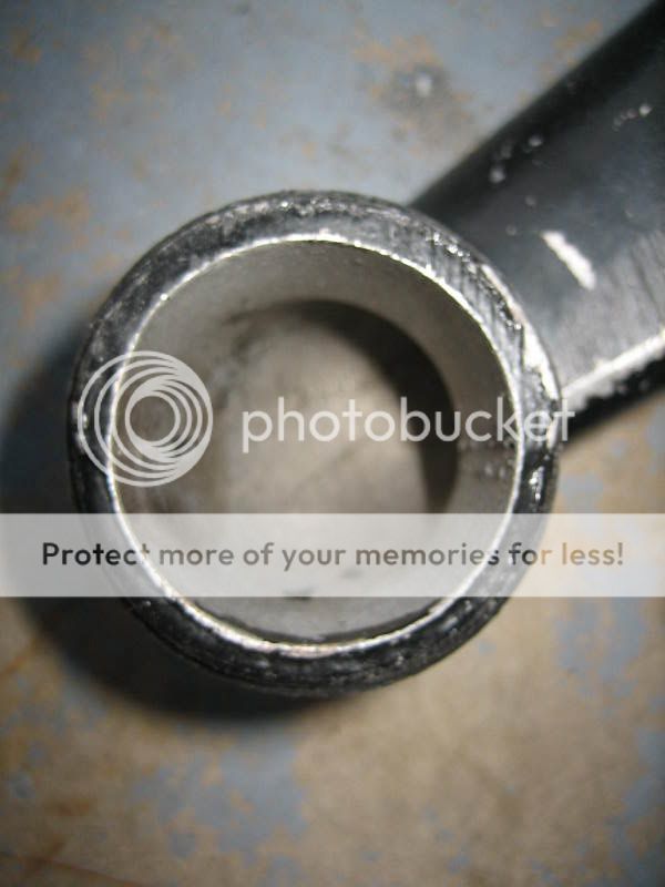
Here is a shot of the stock turbo housing outlet.
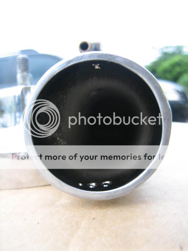
A shot of the leading edge of the stock outlet.

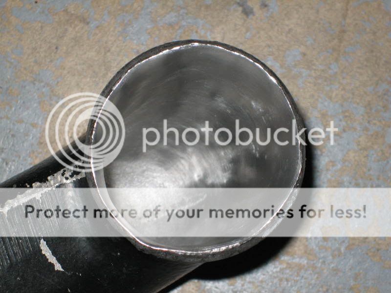
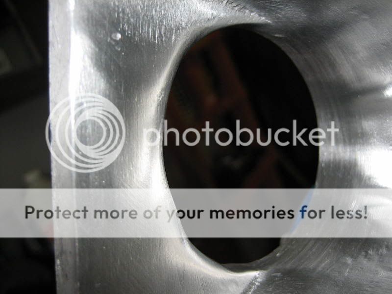
And here is the finished outlet.
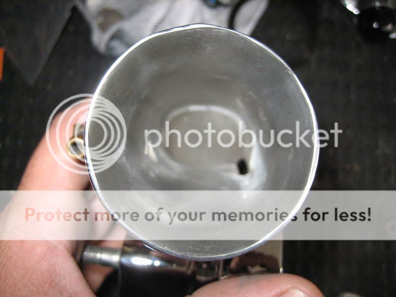
The finished outlet leading edge.

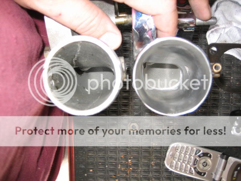
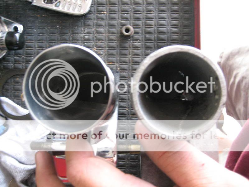
Two comparison shots with my original stock turbo, that I grenaded several months back.
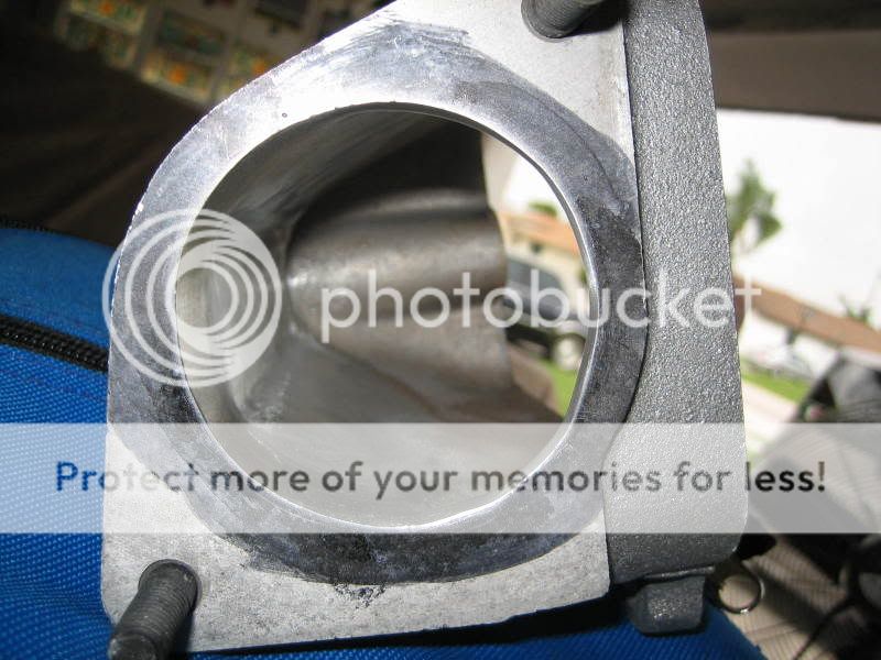
Stock intercooler inlet
Stock intercooler inlet leading edge

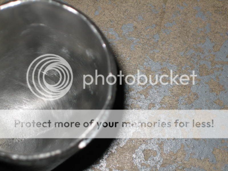
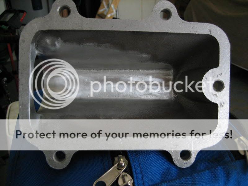
Finished intercooler inlet. I tried to bellmouth it the best I could, but the raised lip was in the way and I didn't want to compromise the strength of the metal. I was able to manage to match the outlet of the turbo to the inlet of the intercooler within a 100th of an inch.
Finished intercooler inlet leading edge.
Here is a shot of the stock turbo housing outlet.
A shot of the leading edge of the stock outlet.
And here is the finished outlet.
The finished outlet leading edge.
Two comparison shots with my original stock turbo, that I grenaded several months back.
Stock intercooler inlet
Stock intercooler inlet leading edge
Finished intercooler inlet. I tried to bellmouth it the best I could, but the raised lip was in the way and I didn't want to compromise the strength of the metal. I was able to manage to match the outlet of the turbo to the inlet of the intercooler within a 100th of an inch.
Finished intercooler inlet leading edge.
Underboost
Mr. Dull
- Joined
- Oct 4, 2005
- Messages
- 4,277
Nice! Good Job! ")
DougsfastZ
4.1
- Joined
- Jan 30, 2004
- Messages
- 727
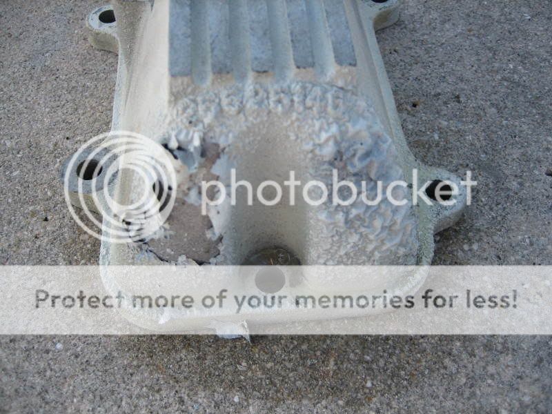
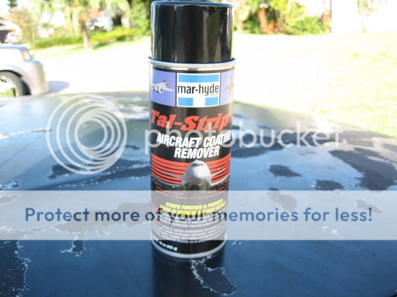
Well, I found out the doghouse and the lower intake were cleared. Not sure if GM did that or if someone else did it over the years, but that's the reason why, when I used Mag wheel etching cleaner, the parts turned ivory. So I went out and bought some aircraft coating remover from Advance Auto and sprayed the parts down. It works very well. In several posts above, you can see what they looked liked before.
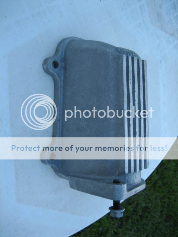
Here is a shot of the dog house, about 15 minutes after spraying the remover. I used a flat blade to see how loose the paint was, and it was pealing off with ease.
This is what I used.
With a garden hose, most of the old paint came off, but some spots were more difficult to remove. So I resprayed the parts a second time and used my pressure cleaner to remove the rest of the paint. Here are the results of the doghouse.
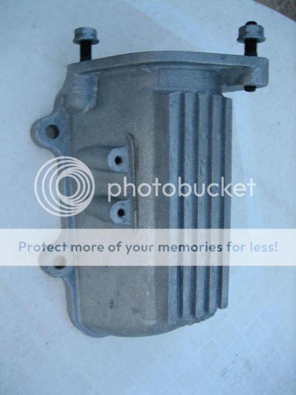
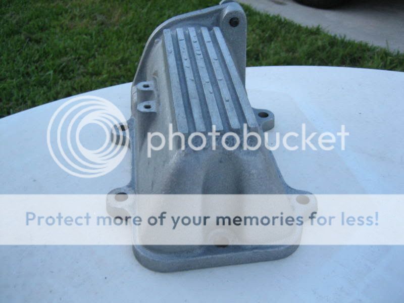
The pictures do no justice, the naked aluminum looks great! The lower intake needs a few more cleaner treatments and pressure washing to be complete. Now that I know all the paint is off, I'll reuse the mag wheel etching cleaner to get the aluminum perfect.
Here is a shot of the dog house, about 15 minutes after spraying the remover. I used a flat blade to see how loose the paint was, and it was pealing off with ease.
This is what I used.
With a garden hose, most of the old paint came off, but some spots were more difficult to remove. So I resprayed the parts a second time and used my pressure cleaner to remove the rest of the paint. Here are the results of the doghouse.
The pictures do no justice, the naked aluminum looks great! The lower intake needs a few more cleaner treatments and pressure washing to be complete. Now that I know all the paint is off, I'll reuse the mag wheel etching cleaner to get the aluminum perfect.
DougsfastZ
4.1
- Joined
- Jan 30, 2004
- Messages
- 727
Today I also worked on the throttlebody. I did a little bit more work then just porting and polishing. I removed the top half of the throttle blade shaft, knife edged the blade itself, then bellmouthed the inlet of the TB. I've done this on several LS1's with great success.
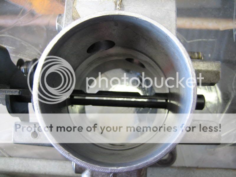
This is a shot of the shaft reinserted. The goal is to remove the top half of the shaft. I spun the shaft so that the half to removed is facing up, then I scribed lines on either side of the shaft where it meets the inside of the thorttle body port. This will let you know where to cut.
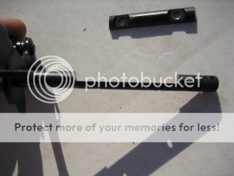
I tooke my cut off wheel and cut on the scribe marks. Here is what the shaft looks like cut.
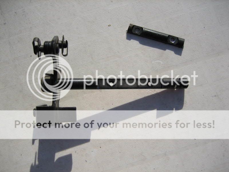
Side shot of the cut shaft.
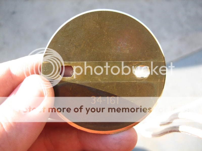
This is a shot of the shaft and blade reinstalled.
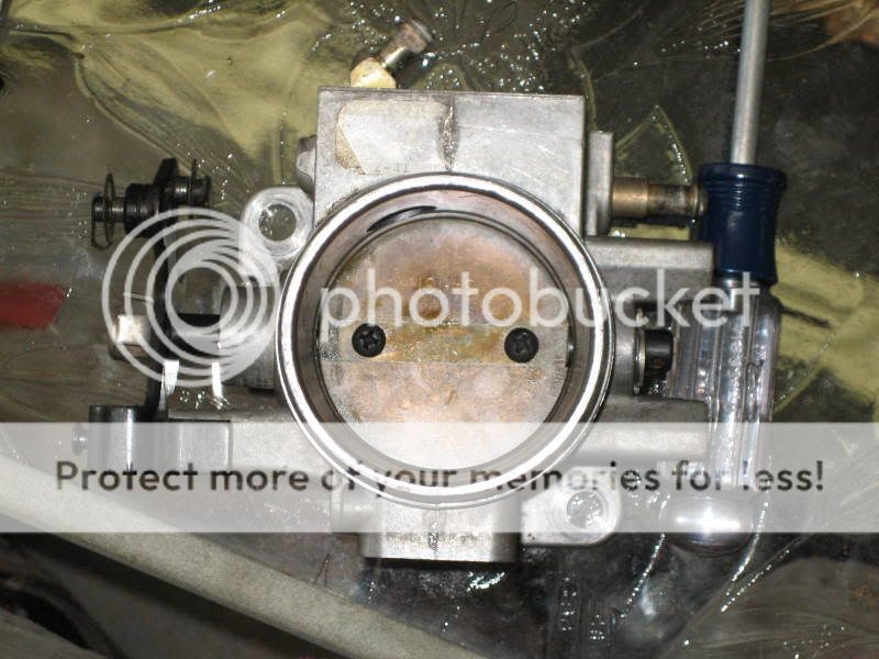
This is what it looks like with the blade open. I plan on going to the hardware store to get the same thread bolts, only with a flush mount head. The I'll use the proper size drill bit, slightly countersink the blade and run the flush mount screws in, nice and flush. Then I'll grind any excess threads showing on the bottom of the shaft, along with some loctite.

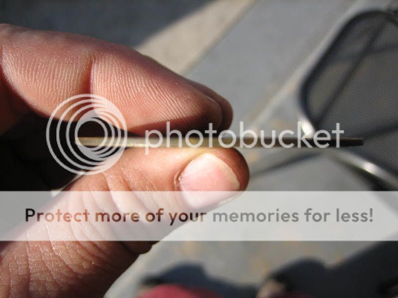
This is the thickness of the stock throttle blade.
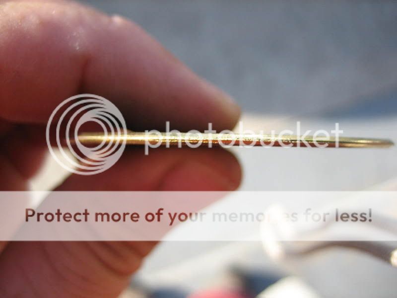
And these are pics of the finished knife edged blade. All I did was carefully make passes back and forth on my bench grinder to get the edge I was looking for. I did both the leading and tail edge of the blade. I did not change the overall diameter of the blade.

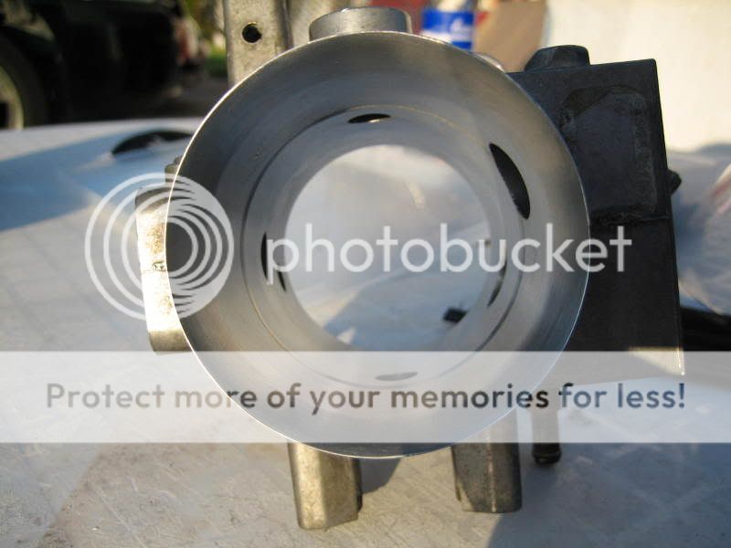
The final thing I did to the TB was bellmouth the inlet, just like the turbo inlet bell. This has been the best port and polish work I've done so far.
This is a shot of the shaft reinserted. The goal is to remove the top half of the shaft. I spun the shaft so that the half to removed is facing up, then I scribed lines on either side of the shaft where it meets the inside of the thorttle body port. This will let you know where to cut.
I tooke my cut off wheel and cut on the scribe marks. Here is what the shaft looks like cut.
Side shot of the cut shaft.
This is a shot of the shaft and blade reinstalled.
This is what it looks like with the blade open. I plan on going to the hardware store to get the same thread bolts, only with a flush mount head. The I'll use the proper size drill bit, slightly countersink the blade and run the flush mount screws in, nice and flush. Then I'll grind any excess threads showing on the bottom of the shaft, along with some loctite.
This is the thickness of the stock throttle blade.
And these are pics of the finished knife edged blade. All I did was carefully make passes back and forth on my bench grinder to get the edge I was looking for. I did both the leading and tail edge of the blade. I did not change the overall diameter of the blade.
The final thing I did to the TB was bellmouth the inlet, just like the turbo inlet bell. This has been the best port and polish work I've done so far.
DougsfastZ
4.1
- Joined
- Jan 30, 2004
- Messages
- 727
nice work:biggrin: how would you compare the port work on the i/c verses a dutneck....in the pics the port work looks great
No comparison. The nutt neck is much larger, I believe 2.5", where my ported opening only went to 1.91".
DougsfastZ
4.1
- Joined
- Jan 30, 2004
- Messages
- 727
Today I worked on the upper intake. I removed the EGR tower, blended the top of it, ported the throttlebody opening, and radiused the inlet down where the EGR tower was.
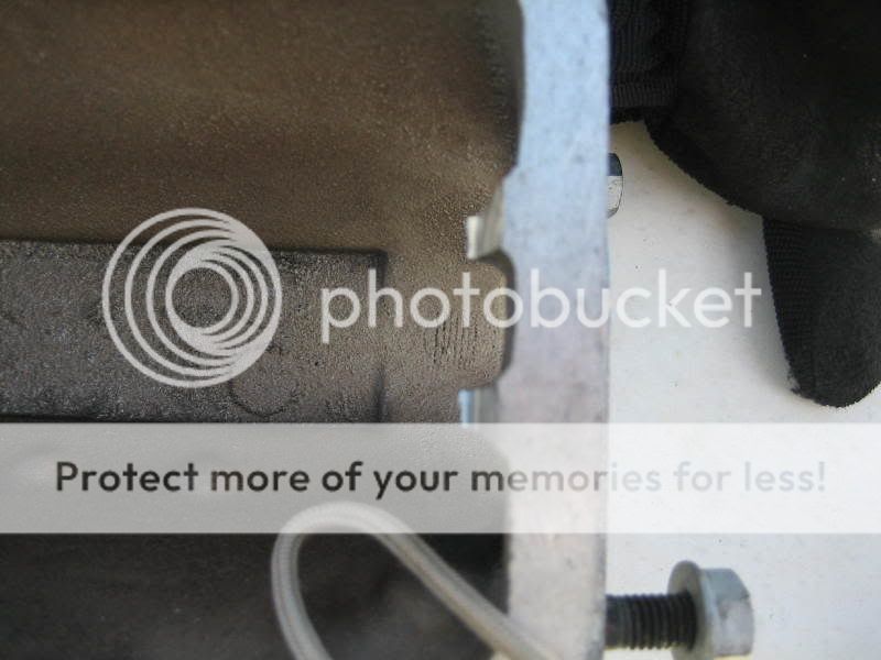
Closeup of the stock EGR tower.
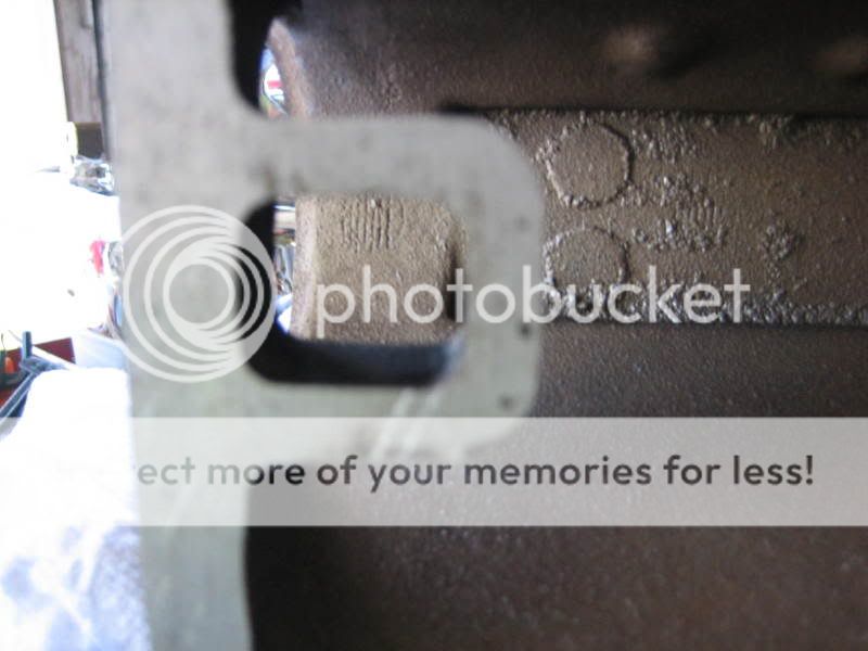
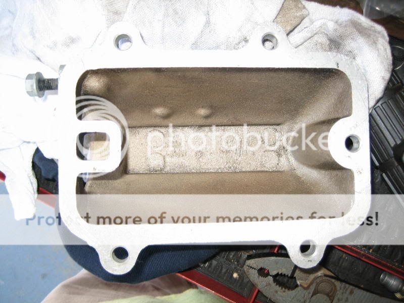
A good picture of the stock inside of the intake.
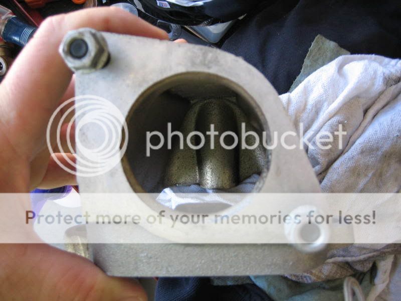
Unported throttlebody opening.
A shot of the EGR tower removed. I simply used a 3" cutoff wheel on my die grinder.
Another shot of the cut.
Finished ported and polished intake.
Shot of how I blended the ridge that ran the length of the intake. I also cut out the nipples that were near the throttle cable bracket holes.
Closeup of the radius I did on the bottom side of the throttlebody opening.
Shot of the throttlebody mocked up to the intake. The transistion is almost seamless.
Closeup of the stock EGR tower.
A good picture of the stock inside of the intake.
Unported throttlebody opening.
A shot of the EGR tower removed. I simply used a 3" cutoff wheel on my die grinder.
Another shot of the cut.
Finished ported and polished intake.
Shot of how I blended the ridge that ran the length of the intake. I also cut out the nipples that were near the throttle cable bracket holes.
Closeup of the radius I did on the bottom side of the throttlebody opening.
Shot of the throttlebody mocked up to the intake. The transistion is almost seamless.
84BuickGNYorkPA
Daily Driving Buick V-6 Turbo's 1979 - Present
- Joined
- Jul 5, 2005
- Messages
- 1,840
Doug,
Check your DS exhaust manifold tranistion to the cross over pipe, mine was oval and restrictive.
And thanks for sharing, I see I have some work to do this Winter.
Chuck
Check your DS exhaust manifold tranistion to the cross over pipe, mine was oval and restrictive.
And thanks for sharing, I see I have some work to do this Winter.
Chuck
Rodney87GN
Well-Known Member
- Joined
- Feb 1, 2004
- Messages
- 1,931
Very nice work!
DougsfastZ
4.1
- Joined
- Jan 30, 2004
- Messages
- 727
Doug,
Check your DS exhaust manifold tranistion to the cross over pipe, mine was oval and restrictive.
And thanks for sharing, I see I have some work to do this Winter.
Chuck
Thanks, I'll look at the transition. I was thinking of opening up the male side of the manifolds where it meets the crossover, but I don't want to cause any leaks.
84BuickGNYorkPA
Daily Driving Buick V-6 Turbo's 1979 - Present
- Joined
- Jul 5, 2005
- Messages
- 1,840
DougsfastZ
4.1
- Joined
- Jan 30, 2004
- Messages
- 727
What is the color difference for removing metal about?
Similar threads
Online statistics
- Members online
- 18
- Guests online
- 2,516
- Total visitors
- 2,534
Totals may include hidden visitors.